p-m interaction diagram
The required axial strength and required moment strength of the ith column are obtained. This example goes through how to create a moment-axial load interaction diagram for a reinforced concrete column.

Axial Load Bending Moment P M Interaction Diagram Download Scientific Diagram
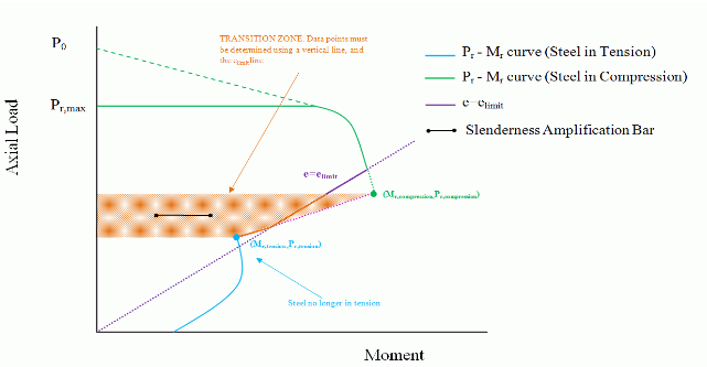
P-M diagra always consider case where cd but bound maximum allowed response to PrMax cutout at PPrMax Dont forget that everything above balanced condition.
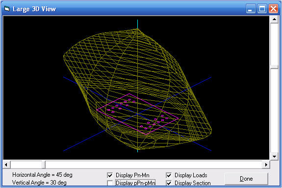
. SAP2000 P-M interaction diagram in capturing. This is helpful for creating home. To simplify interaction-surface data users may fix values or ratios between values to consider 2D curves which represent section cuts through the 3D surface.
Generally the strength check of the RC columns utilizes a P-M interaction diagram as shown in Fig. The points found in this example are A pu. Dear ankurjain1 we are implementing an automatic tool in python to draw the P-M interaction diagram we will release it next fall.
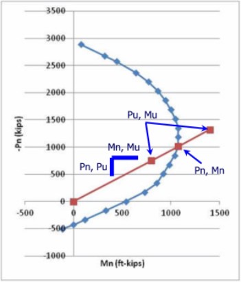
P-M interaction diagrams determine the capacity envelope of a reinforced concrete member with a combination of axial force and moment applied at a section of the member. Kramer Calculate P n M n by applying forces to free body diagram 7995 kips 8943 kips 48960 kips Moment. It can be observed that the analytical P-M interaction diagrams slightly underestimated the experimental P-M interaction diagrams for Group GS40 under concentric.
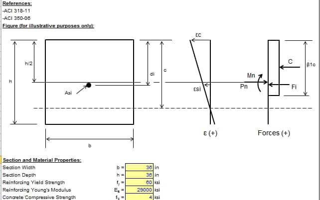
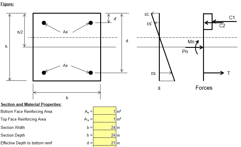
Introduction The P-M interaction diagramcurve is used to design reinforced concrete members in which axial force and bending moment act simultaneously. This problem shows the calculations and steps necessary to create an interaction diagram for a reinforced concrete column. 1 By prestressing column the.
This example problem goes through how to develop a moment-axial force interaction diagram for a reinforced concrete column with three layers of steel. The P-M interaction diagram for unreinforced masonry walls is created in three separate stages. Design code Section diameter in.
Meanwhile you can draw it manually. Interaction Diagrams for Concrete Columns DD. The variation in the base shear capacity is less than 10 while variation in displacement capacity is.
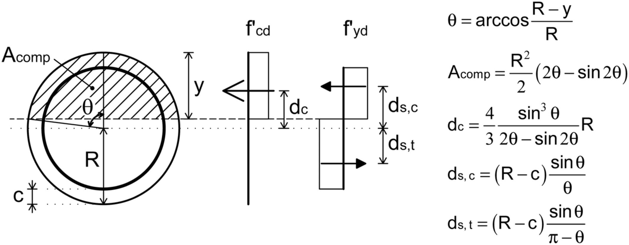
The first stage where the wall must remain uncracked the curve is under the e limit line. P-M Diagram for Circular Columns Based on AASTHO LRFD 8th Edition ACI 318-14 Input Parameters.

P M Interaction Diagram Of A Rectangular Concrete Column Maple Application Center
Aci 318 350 P M Interaction Diagram Us Customary Units 2 1 Sipilpedia

Carbon Fiber Reinforced Polymer Strengthened Reinforced Concrete Square Columns Under Pre Existing Eccentric Loads Nima Kian Masood Farzam Mohammad Rezaie Oshtolagh 2021

Pdf Bending Axis Effects On Load Moment Pm Interaction Diagrams For Circular Concrete Columns Using A Limited Number Of Longitudinal Reinforcing Bars Semantic Scholar

8 Example 2 M N Interaction Diagram For Concrete Column With Three Steel Layers Youtube
A Simple Method For N M Interaction Diagrams Of Circular Reinforced Concrete Cross Sections Engissol Ltd Structural Engineering Software

Interaction Diagram Sap2000 Computers And Structures Inc Technical Knowledge Base
P M Interaction Diagrams Of The Column Base With A Design Resistance Download Scientific Diagram
Interaction Diagrams
Beam Column Design Excel Spreadsheet Per Aci 318 And Aci 350 Civilengineeringbible Com
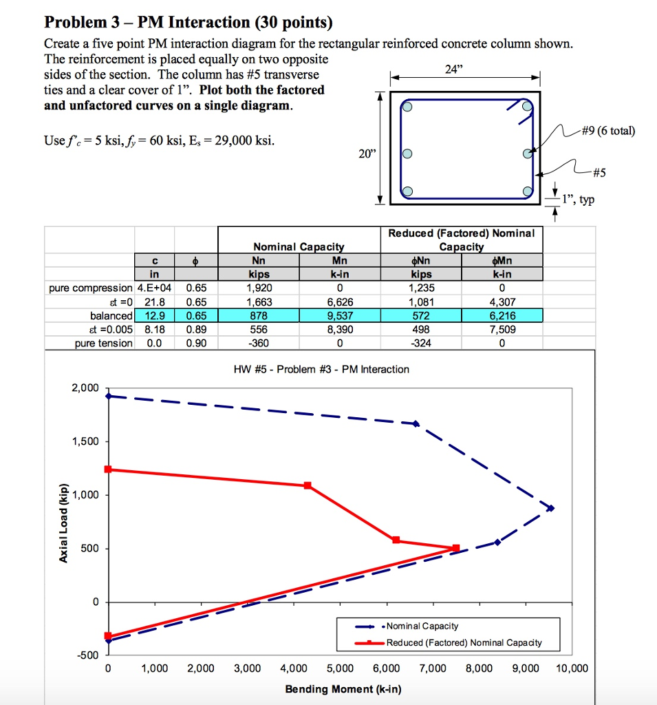
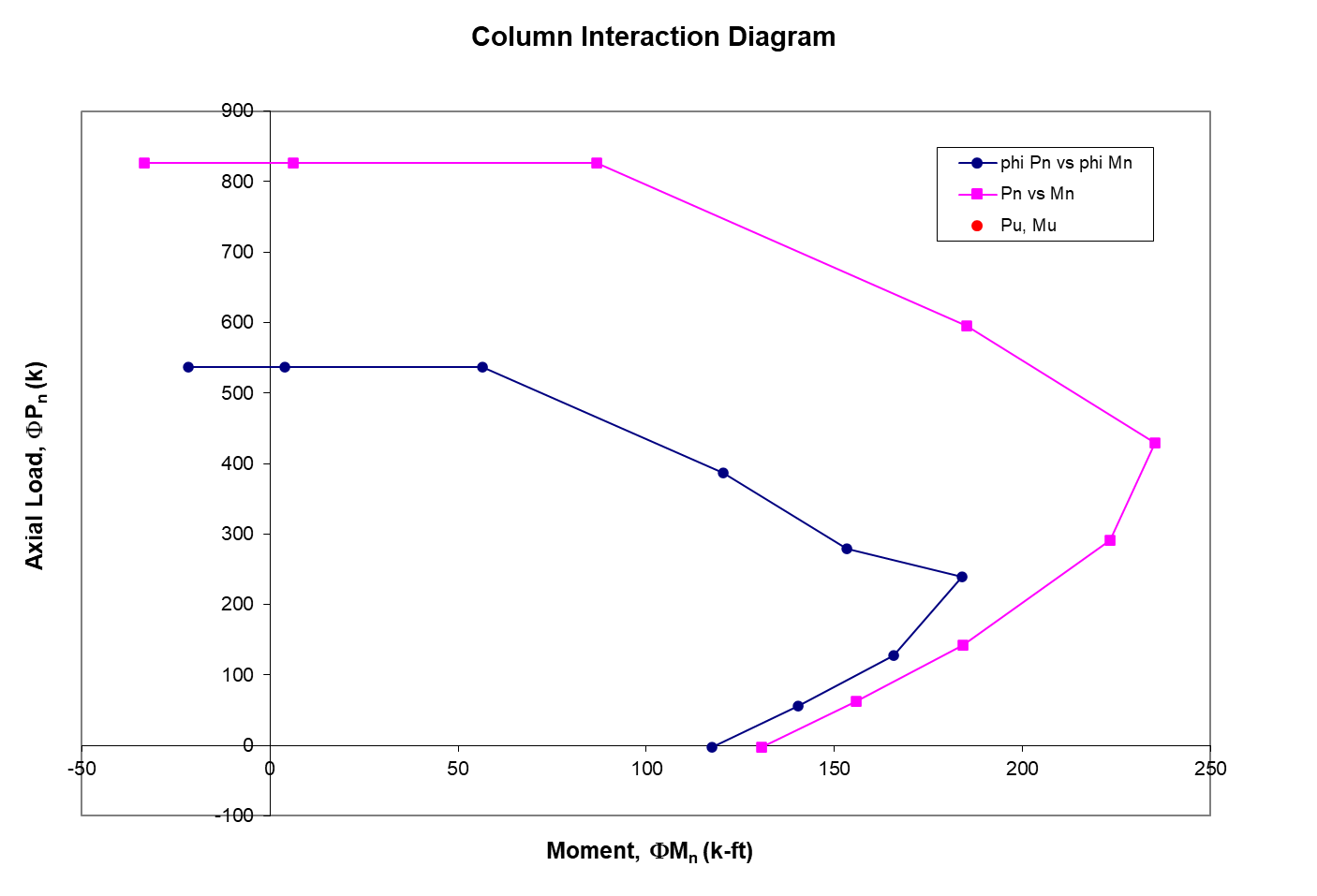
Solved Problem 3 Pm Interaction 30 Points Create A Five Chegg Com

Interaction Curve
P M Interaction Curve For Rcc Column
P M Interaction Diagram Mass User Documentation
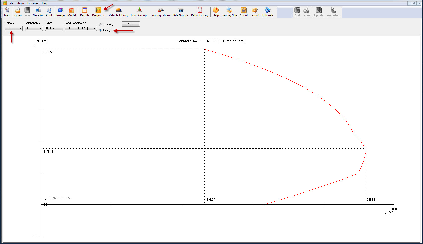
Moment Shear And Interaction Diagrams Lars Leap Openbridge Opentunnel Rm Wiki Lars Leap Openbridge Opentunnel Rm Bentley Communities

Design Of Rc Columns Using Glass Frp Reinforcement Journal Of Composites For Construction Vol 17 No 3

Simplified Linear P M Interaction Diagram Download Scientific Diagram